|
|
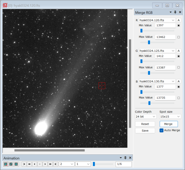
Merge RGB Images The Merge RGB Images command creates an RGB color image by merging 3 separate images interpreted as the red, green, and blue channel data. The source images are taken from an Image Set opened in the source Image Window. The new RGB image is opened in a new Image Window. The merging process uses parameters adjusted in a docking pane attached to the Image Window. This process is essentially a matter of choosing the black level and white level for each of the channel images, hence the docking pane includes several controls for setting these levels for the component images. The picture below shows the Merge RGB pane opened for a window containing several of the sample images. Also see the example near the bottom of the page.
OverviewThe strategy behind this command is to adjust the minimum pixel value and maximum pixel value for the channel images. For merging the channel images, these values correspond to the values that will become the black and "white" (or maximum color) levels, respectively. Setting the minimum and maximum pixel values effectively changes the contrast and brightness of each channel in the merged LRGB image. The values in the text fields are used for merging, regardless of how they are set. Beyond simply typing a number into each text field, several controls are provided for setting these values. The following table shows several ways to adjust the minimum and maximum pixel values for the R channel image. These same controls are provided for all three channels.
The [Merge] button scales each of the images using minimum and maximum values from the text fields. The Auto Merge check box enables automatic merging after changing any of the six trackbars. When the channels are merged, Mira creates the new RGB image in a new Image Window. If the images are merged again, the new RGB image overwrites the previous RGB image in the window. The final color brightness, contrast, and color balance of the RGB image can be refined using the Palette Properties dialog for the output window. The [Save] and [Reset] buttons save and re-load the parameters below the horizontal line. Procedure for Merging Images
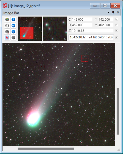
Example: Showing Object MotionRGB Merging is useful for data visualization tasks beyond simply creating a color image from filtered monochrome images. This example illustrates how motion of Comet Hyakutake (Comet C/1996 B2) may be quickly visualized by merging 3 exposures acquired at different times. After loading the Hyakutake sample images provided with the Mira installation (see the Image Window above), the first, middle, and last images were selected as the R, G, and B channels. The names of these files represent a time sequence, so images 120, 135, and 145 were chosen to mark the beginning, middle, and end of the exposure sequence. Mira calculates the default black and white levels when an image is selected, so no other adjustments were made. In the merged RGB image below, notice how the first (red) image shows the beginning position while the last (blue) image shows the final position of motion relative to the stars. Note that the color of the R and B channel images is shifted toward green by the overlapping middle image used for the G channel.
Related Topics
Mira Pro x64 8.71 User's Guide, Copyright Ⓒ 2024 Mirametrics, Inc.
All Rights Reserved. | ||||||||||||||||||||||