![]() Point
Measurements
Point
Measurements
The Point Measurement tool measures a
collection of point coordinates and values on an image. In addition
to reporting the pixel value, or "intensity", the pixel coordinates
are reported in both (column,row) and world coordinates
if the image has a world coordinate calibration. The coordinates
are marked using the mouse crosshair or may be precision centroid
coordinates computed near the clicked point. This command is like
the Centroid
measurement affiliated with the Image Cursor except this command operates from
a toolbar and the the points are persistent until you leave the
Points mode by closing the toolbar. This command allows many points
to be drawn on the image whereas the centroid marks only one point
at a time . Results are reported in the Points Measurement Pane. The
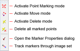
toolbar opens in Marking Mode wth the top button active. Marker
properties are set in the Marker Properties dialog opened from the ![]() button on the Points toolbar.
button on the Points toolbar.
To activate the Point Measurements
toolbar, click ![]() on the Image Measurements Toolbar or use Measure >
Points command on the main menu.
on the Image Measurements Toolbar or use Measure >
Points command on the main menu.
The following picture shows an Image Window with several points marked on the image. Notice the Point Measurements Toolbar docked on the left border of the Image Window.
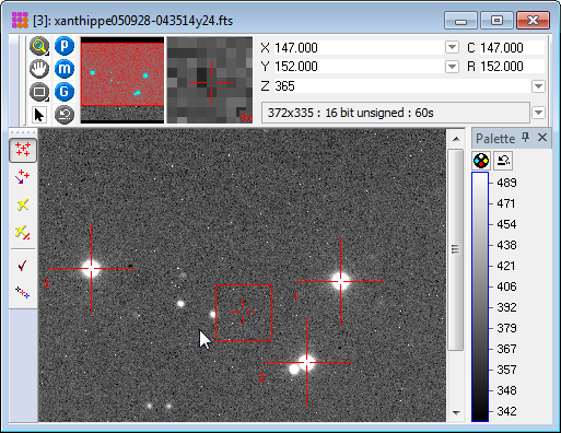
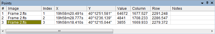
The 3 points marked above created a
Points Measurement Pane where the results are listed.
Results can also be diverted to a top-level Report Window using the
option in the Marker Properties dialog opened using the ![]() toolbar button.
toolbar button.
First, make sure Point Measurement command.
First, be sure the Drawing and Centroiding
properties are set as desired. To open the Marker Properties
dialog, click ![]() on the toolbar.
on the toolbar.
If Marking Mode is
not active, click the ![]() button on the
window toolbar (not the Image Measurements
Toolbar).
button on the
window toolbar (not the Image Measurements
Toolbar).
Move the mouse pointer to each target point and click the left mouse button.
Repeat for each target point on the image.
To move an existing point, click ![]() on the Points toolbar to enter
Move mode, then drag a marker to a
new position and drop it there. If centroiding is enabled in the
Marker
Properties dialog, the marker will automatically centroid on
near the point where it is dropped.
on the Points toolbar to enter
Move mode, then drag a marker to a
new position and drop it there. If centroiding is enabled in the
Marker
Properties dialog, the marker will automatically centroid on
near the point where it is dropped.
If points are no longer needed, click ![]() to enter Delete mode and click on the points to
remove them.
to enter Delete mode and click on the points to
remove them.
To track marked points through an image set,
click ![]() on the toolbar.
on the toolbar.
To re-enter marking mode, click ![]() on the toolbar.
on the toolbar.
To disable all toolbar modes for Point
Measurements, click ![]() on the Image Bar or select
Disable Modes from the Image Context
Menu.
on the Image Bar or select
Disable Modes from the Image Context
Menu.
Measurements are tabulated in the Points pane as shown above. Using this window, the measurements may be sorted, rearranged, saved to the clipboard or a file, etc.
If the image has a World Coordinate System ("WCS") calibration and the Centroid First Point box is checked in the Point Properties dialog , then (X,Y) is a centroid position computed from the centroid (column,row) position.
The items in the Report are described in the table below.
Point Measurements Column Data
|
# |
The sequence number of the measurement. |
|
Image |
The name of the image that was measured |
|
Distance |
The distance in pixel units, or arcseconds if the image has a WCS calibration. |
|
Index |
By default, Mira fills this column with a sequential number which is the index of the point starting at 1. However, unlike the # column, which cannot be edited, this entry can be edited to give the point any identifier which then would be included in a saved or copied report. |
|
X |
The X coordinate of the point in world coordinates. If no world coordinate calibration exists, the value is the column position. |
|
Y |
The Y coordinate of the point in world coordinates. If no world coordinate calibration exists, the value is the row position.. |
|
Value |
The value of the pixel at (X,Y). |
|
Col |
The column coordinate of the point. |
|
Row |
The row coordinate of the point. |
Measuring Images, Distance & Angle Measurements, Plot Point Query, Measurement Panes, Image Windows, Pixel Coordinate Definition, Sub Pixel Coordinate Definition, World Coordinate System