![]() Angle
Measurements
Angle
Measurements
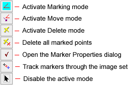
The Angle Measurement tool measures the included angle and base angle between two intersecting angles. The vertex and endpoint coordinates are reported in both (column,row) and world coordinates for images having a world coordinate calibration. Coordinates are marked using the mouse crosshair and may be refined using precision centroid coordinates computed near the clicked point. Angles drawn on the image are persistent until you leave Angles mode by closing the toolbar. Results are reported in the Angles Measurement Pane or Angle Measurements report window. The toolbar opens with Marking Mode (top button) active. Angles may also be measured using the CMeasureAngles class in the Pro Script Module. See the Mira Pro x64 Script User's Guide.
To activate the Angle Measurement tool,
click ![]() on the Image Measurements
Toolbar or click Angles in the Measure menu.
on the Image Measurements
Toolbar or click Angles in the Measure menu.
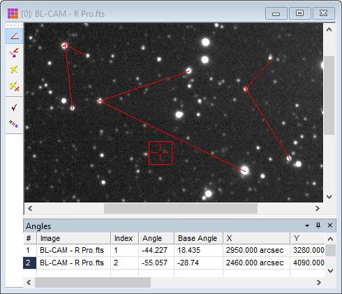
The picture below shows several angles marked on an image. The results may be directed to a measurement pane or report window, as described below.
The basic procedure for drawing angles is as follows:
Mouse down at the vertex.
Holding the mouse down, move to the endpoint of the first line and release.
Without pressing the mouse buttons, move to the end of the second line.
Click the mouse at the endpoint of the second line.
Here a more detailed procedure:
Adjust the image to the desired magnification, image position, palette, and other attributes.
Click the ![]() button on the Image Measurements Toolbar or use the Measure > Angles Toolbar menu command to open
the toolbar. Marking mode is automatically enabled when the toolbar
is opened. If marking mode has been disabled by prior commands,
activate it by clicking the
button on the Image Measurements Toolbar or use the Measure > Angles Toolbar menu command to open
the toolbar. Marking mode is automatically enabled when the toolbar
is opened. If marking mode has been disabled by prior commands,
activate it by clicking the ![]() button.
button.
Move the mouse to the vertex point where both lines will intersect. At the vertex point, press and hold down the left mouse button. If Centroid First Point is enabled in the Marker Properties dialog, the position will lock onto the local centroid near where the mouse is released.
With the left button down, drag the cursor to the endpoint of the first side. Release the button at the endpoint to draw the first side. If Centroid Last Point is enabled in the Marker Properties dialog, the position will lock onto the local centroid near where the mouse is released.
Move the mouse to the endpoint of the other side of the angle marker. Click the mouse to mark the endpoint. The angle measurement is reported in the Angle Measurements window or Angles measurement pane in the Image Window. If Centroid Last Point is enabled in the Marker Properties dialog, the position will lock onto the local centroid near where the mouse is released. The results are reported in the measurement pane or window.
To measure other angles, repeat steps 3 though 5.
When finished you can disable marking mode by
clicking ![]() on the toolbar.
on the toolbar.
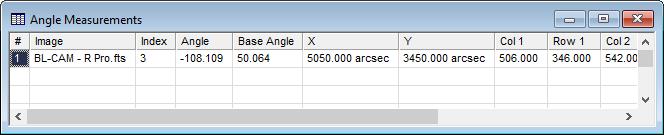
Measurements are tabulated in either the Angle Measurements measurement pane owned by the Image Window as shown above, or a Report Window as shown below. The difference between the two output options is that the Angles measurement pane receives only measurements of that Image Window whereas the Angle Measurements window is global and receives measurements from all Image Windows.
If the image has a World Coordinate System ("WCS") calibration, then X1, X2, Y1, and Y2 give the WCS values corresponding to listed column,row coordinates.
Column data in the Angles pane and Angle Measurements report are described in the table below. The last few columns from the table below are not scrolled into view in the picture above.
|
Angle Measurements Column Data |
|
|
# |
The sequence number of the measurement. |
|
Image |
The name of the image that was measured. |
|
Index |
The marker index for the particular image. |
|
Angle |
The "included" angle in degrees measured between the two line segments. |
|
Base Angle |
The angle between horizontal and the line segment drawn first. This is calculated between the vertex Col1,Row1 (or X1, Y1 in world coordinates) and Col2, Row2. |
|
X |
The World (or pixel) X coordinate at the vertex of the angle marker. This is the point where the 2 side vectors intersect. If the image has no WCS calibration, this is the column coordinate. |
|
Y |
The World (or pixel) Y coordinate at the vertex of the angle marker. This is the point where the 2 side vectors intersect. If the image has no WCS calibration, this is the row coordinate. |
|
Col 1 |
The column coordinate of the starting point (vertex). |
|
Row 1 |
The row coordinate of the starting point (vertex). |
|
Col 2 |
The column coordinate of the ending point of the first side drawn (ending at Col2, Row1). |
|
Row 2 |
The row coordinate of the ending point of the first side drawn (ending at Col2, Row2). |
|
Col 3 |
The column coordinate of the ending point of the last side drawn (ending at Col3, Row3). |
|
Row 3 |
The row coordinate of the ending point of the last side drawn (ending at Col3, Row3). |
|
Notes |
Space to add comments about the measurements. These will be included if you export the table to a text file. |
As with other interactive marking commands, the
Angle Measurements command can use the exact marked
coordinates or it can compute the coordinates as a precise centroid
positions. To set these options, click ![]() on the toolbar to open the
Marker Properties dialog for this command, then set Centroid First Point
or Centroid Last Point accordingly.
on the toolbar to open the
Marker Properties dialog for this command, then set Centroid First Point
or Centroid Last Point accordingly.
Mira Pro x64 User's Guide, Copyright Ⓒ 2023 Mirametrics, Inc. All
Rights Reserved.