Magnitude Calculations
This topic describes how the Aperture Photometry
package calculates the magnitudes and their random errors (or
"uncertainties"). These quantities, as related to the table of
photometry results, are also described in the topics Photometric
Measurement Definitions and Photometric Error
Definitions. This topic describes the math behind the
calculations and how apertures are measured on an image.
Calculating the Magnitude
Mira computes the magnitude as
m = K – 2.5 log (
Flux )
where
The camera gain ("Gain") and exposure time
("Exptime") are obtained from the FITS keywords GAIN and EXPTIME.
The value of Counts is the net signal from the object, above the
sky background, and measured in the raw pixel value units (often
called "ADU's"). The Flux therefore represents a total number of
electrons per second attributable to the object, above the sky. To
compute the Flux, the image signal is summed over all pixels inside
the innermost aperture, including the partially filled pixels along
the rim of the aperture (see below). From this sum is subtracted
the estimated sky brightness which is computed from pixels in the
sky annulus formed between the 2 outer apertures. If the GAIN and
EXPTIME keywords are not present in the image header, or they are
wrong, you can add them or edit them using the Image Information page of the Aperture Photometry Properties dialog. Also
see the topic Fixing Header
Problems in Photometric Data. You can also change the
names used for fetching the GAIN, EXPTIME, and RDNOISE values using
the Photometry
Keywords dialog.
The value K is the photometric zero point. The zero
point is assumed to be 0 or the value of the ZERO-PT keyword in the
image header. If the value is 0, then the magnitude may be called a
"raw magnitude". If a zero point value is computed for a particular
instrumental setup and used in the calculation, the result is
called "instrumental magnitude". If the zero point value, K, is
unknown, it may be calculated using standard stars of known
magnitude.
Magnitude Errors
The uncertainty of the magnitude measurement is
calculated in two ways: an empirical error, listed in the
Apphot Measurements Pane as Error, and a theoretical value listed as
Error(T). The reported values may or
may not include the uncertainty in the photometric zero point,
which is calculated when more than 1 standard star is used. This
option is controlled by the Include Zero
Point Error check box on the Other
Properties page. If checked, the reported error is the Root Sum
Square ("RSS") value of the internal error of the measurement and
the error of the mean of the zero point. The latter value is
reported in the Photometry Results window.
The empirical error involves the noise measured in
the sky annulus as well as the values of GAIN, RDNOISE, and EXPTIME
from the image header. The theoretical error uses the keywords but
not the measured sky noise. The theoretical error estimate is the
minimum possible uncertainty that could be measured at a given
magnitude. You can change the values of GAIN, EXPTIME, and RDNOISE
on the Image
Information page. Doing so will change the error values
by a small amount.
Description of the Apertures
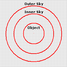
The aperture photometry procedure uses 3 apertures
to measure an object:
-
The central aperture measures the total signal
for the object. It does not have to enclose all the light from the
object, so long as all objects on the image are measured using the
same aperture.
-
The outer 2 apertures forms a ring, or annulus,
inside of which the local sky (background) is measured. This is
subtracted from the total signal inside the object aperture.
|
|
Diagram of a "measuring aperture" formed by an
object aperture and a sky sampling region between two outer
apertures.
The inner sky aperture should begin beyond the
light in the star profile. However, the sky measuring ring should
not be placed so far that it includes many other stars or that it
samples sky that is not the same as that underneath the object.
|
The inner, object measuring aperture can be
adjusted to any radius but, generally, it should not extend all the
way to the point where the star appears to merge into the sky
noise. Use the following guidelines to size the object
aperture:
-
The fraction of the object's total light being
measured does not vary over the region of the image(s) being
measured.
-
The same size aperture is used foe measuring
every object. Mira automatically handles this.
Regarding item 1, the object aperture can cut onto
the star profile so long as it does the same for all star profiles.
You can be totally safe by making the object aperture large enough
to contain "all the light", but this adds more sky noise, which
lowers the precision of the measurement and makes the magnitude
errors larger. On the other hand, if the star profile varies over
the region being measured, you might use an object aperture large
enough to hold all the light for bright objects, or as the only
option for measuring the field of view.
The aperture photometry procedure uses 3 apertures
to measure the object. The central aperture measures the total
signal for the object while the local background is measure in the
annulus between the outer two apertures. The apertures may be
circular or elliptical, with any ellipticity and angle of rotation,
but all three apertures have the same shape and are concentric.
Elliptical apertures are used to measure objects when the Point
Spread Function ("PSF") is elongated by poor tracking or other
reasons. Matching the ellipse to the PSF shape gives a better
measurement by maximizing the signal through the aperture of a
given area, which in turn maximizes the signal to noise ratio.
Small Apertures
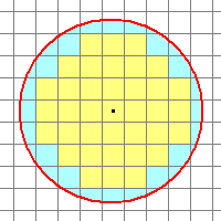
The general placement of a measuring aperture on
the pixel grid is shown below. In general, the object aperture,
whether elliptical or circular, or at whatever angle, will have
partially sampled pixels along its rim. For small apertures, a good
measurement depends upon correctly accounting for the partial pixel
coverage. Mira properly accounts for this case using a
mathematically complex, but exact partial pixel algorithm—the only
one of its kind.
|
|
Enlarged view of the object aperture. The star's
light profile is assumed to extend outside the picture. so the
aperture does not contain all the light from the star. Many pixels
fall along the rim and are only partially measured by the
aperture.
Yellow: Fully sampled pixels.
Blue: Partially sampled pixels.
|
The Ellipticity
parameter is defined in terms of the axis ratio of the ellipse: for
semimajor axis a and semiminor axis b, the
Ellipticity is
E = 1 - b/a.
A circle has an ellipticity of 0. The major axis
orientation and the "size" are adjustable using the Aperture Tool window. The
size of an aperture is set as the "radius" defined as follows:
Radius = square root(
semimajor axis * semiminor axis ) = square root ( a * b ).
All 3 apertures use the same Properties for every
measurement. If measuring an image set, the Properties are the same for all
images.
Related Topics
Aperture Photometry, Photometric
Measurement Definitions, Photometric Error
Definitions